Trading and engineering company focusing on process pumps
Network project Power to X Siemens Germesa/Technological Institute.
Calculation of cooling water demand, heat exchanger and pump technology for Power to X (hereinafter referred to as PTX)
Under the project management of the Danish Technological Institute, Copenhagen Pump calculated the cooling water requirement for cooling the heat loss resulting from the electrolysis production of Hydrogen/Hydrogen (H2). We assessed the MTBF Mean time between failures for a plant lifetime of 25 years and the hydraulic challenges of Open Loop and Closed Loop systems.
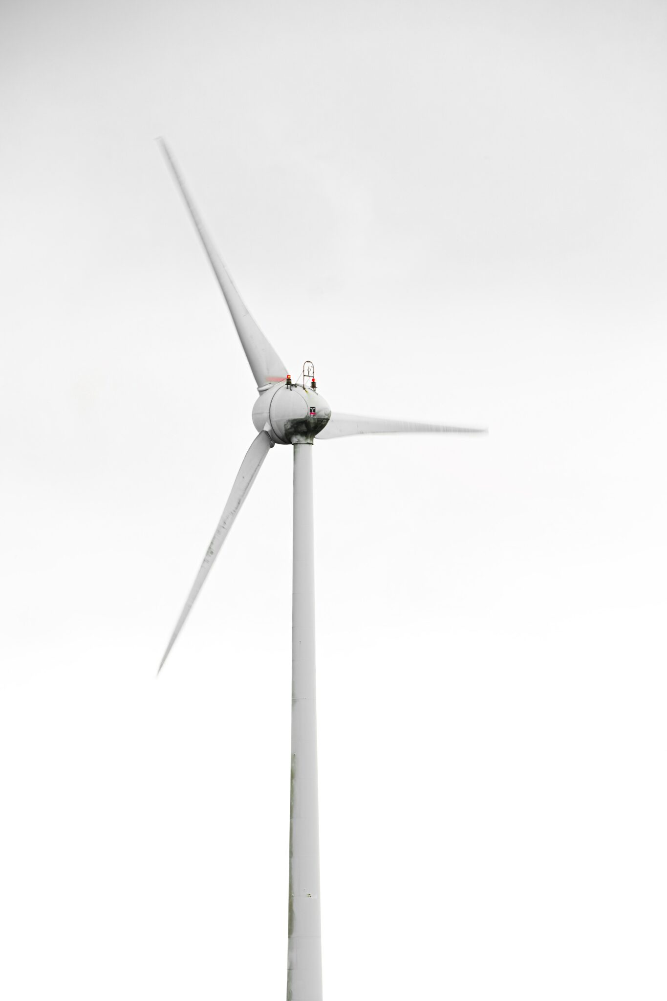
The calculations were performed on a 500 MW and a 21 MW PTX load of offshore wind turbines.
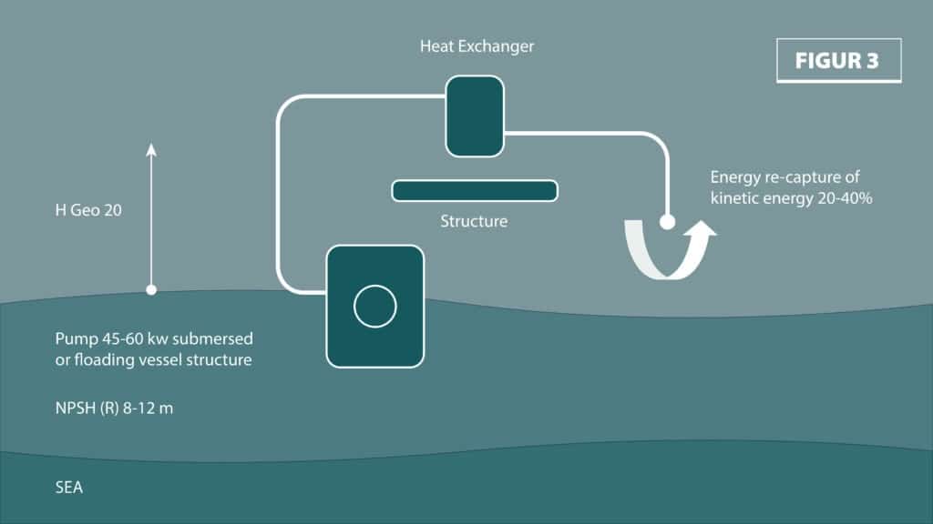
Using the 3 sketches below, we explained the pros and cons. We gave recommendations for pumps and heat exchanger solutions, illustrated C02 foot print, energy loss, maintenance etc.
The two heat exchanger solutions we evaluated were a traditional plate heat exchanger (open loop) versus a submerged tube cooler (closed loop). We also considered the pumping solutions and the hydraulic challenges derived from this.
We have involved leading experts from manufacturers, our private network, consulting engineering companies and universities abroad specializing in relevant physics.
We work from a model where we get an overview of the relevant physics, commercial needs and derive the technical challenges and technical solutions. We have a special focus on utilization and conversion of energy and maintenance.
Below are parts of the conclusion:
Conclusion:
Written by Thorbjørn Schrøder General Manger Copenhagen Pump
Chief Engineer/EBA.
Pumps, pumping technology, hydraulic considerations, seawater cooler, fouling, maintenance, energy consumption.
Based on the assignment from the Danish Technological Institute 500 MW(h) PTX plant at Siemens Germesa/Green Hydrogen, I have investigated different technologies and challenges based on open loop and closed loop illustrated by fig1, fig2 and fig3.
Since no other technical data was available, I have assumed 2 basic load scenarios based on 500 MWH
A)500 MWh over 24 h
B) 500 MW constant load.
Cooling water loss 20% of the produced power
Seabed delta P 12C
Cooling water/glycol 30% delta T 60-40C
Geometric lifting height 20 m
Friction bar 1 bar
Calculated pump power approx. 1 MW corresponding to 1-2/1000
With standard calorimetric calculation Q= MxCxΔT, these conditions result in 71.6 m3/h per 1 MW cooling capacity
500 MWh over 24 h (20.83 MW) gives a cooling water loss of 4.16 MW,
corresponding to cooling water consumption of 297 m3/h
500 MW gives a cooling water consumption of 7128 m3/h for 100 MW cooling water loss.
The pump power at 3 bar is approx. 1 MW where closed loop can save 2/3
At an electricity price of DKK 1 and 8760 tons/year, this corresponds to an operating cost of 1000DKK/hour or approx. 9 mil. and the savings will be approximately DKK 6 mil. The simple payback time is thus 23 years, but without taking other costs into account, it will require a comprehensive technical analysis to correctly assess the cost structure of the alternatives. However, it should be noted that a legal ban on Open Loop is not at all unlikely.
The cooling water consumption can be divided into decentralized systems where each turbine or a few turbines have their own independent cooling circuit of 297 m3/h or a central cooling center/production platform of 7128 m3/h.
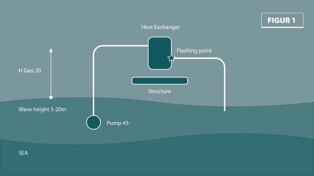
For both scenarios, you have to choose between two technologies A) Open Loop B) Closed Loop
For Open Loop fig 1, the kinetic energy cannot be easily and cheaply returned and in practice this means that you have to pay it for the geometric lifting height in the example of 2o m.
The physical argument can be found in the mechanical physics of pressure and heat theory where the vapor pressure of -1 bar is obtained at -10 m, whereby the two liquid columns lose each other. Water is able to absorb compressive forces, but not tensile forces. This is a mistake that can be overlooked, as even in open loop systems you can subtract the drop height for systems with less than 10 m delta H. This is how a siphon works.
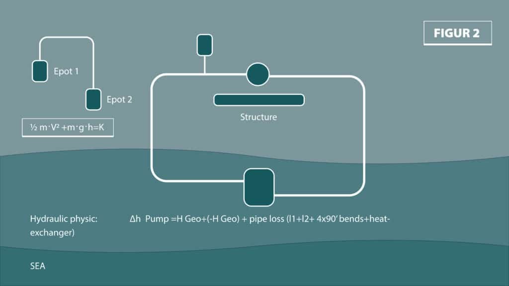
For Closed Loop fig 2, the two geometric lift heights cancel each other out and you only have to pay for the friction loss.
The physical argument is found in the law of conservation of energy.
It is theoretically possible to recover some of the kinetic energy at the bottom of the open loop with a turbine. From theory on the conversion of kinetic energy in wing-driven machines, we know that a maximum of 60% of the kinetic energy can be converted theoretically and in practice for small machines much less, so it is not commercially feasible to attempt energy recapture as shown in Figure 3. However, there is equipment for this purpose, typically propeller turbines.
Heat exchangers:
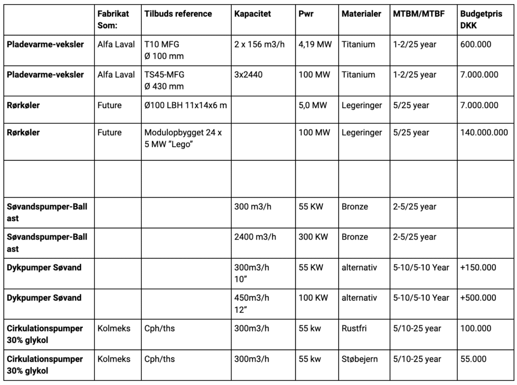
I have spoken to a manufacturer of plate heat exchangers Alfa Laval and the two cooling water scenarios are absolutely realizable and known technology from the oil industry and shipping respectively. In terms of maintenance and service life of 25 years, annual inspection, disassembly and mechanical cleaning/high-pressure cleaning must be expected for 1-2 years.
Thermally the technology works well and is known technology. Fouling between the plates is not highly rated by the manufacturer, while in the inlet it will be more typical and it is recommended to install automatic/sequential back flushing equipment.
My overall assessment and experience with the plate heat exchanger is that it is a solid solution.
Pricing
4-5 MW 300 m3/h DKK 600,000
100 MW 7-10000 m3/h 6-8.000.000
Seawater pumps:
There are two options for installing seawater pumps.
There are pros and cons to both solutions. The lifespan of the submersible pump is typically somewhat shorter and not maintenance-free.
The traditional bronze ballast/fire/seawater pump typically lasts for 25 years with periodic maintenance on shaft seals.
The pumps are available up to about 2400 m3/h where 4 pumps can cover 500 mw demand of 7-10,000 m3/h
300 m3/h pumps for 20 mw demand are standard ship pumps with 55 kW electric motors.
If you choose a centralized solution with 7-10,000 m3/h, my assessment is that a hull installation* below the waterline, of a few large pumps, will provide the most problem-free pumping solution**, while the decentralized solution is probably easier to solve with 10-12" submersible pumps.
*Consider wave height, building heights and technical solution in general. Possibly consider a floating platform or ship, rather than a standing platform. This solution may also be considered together with new clear and compression plants for high-pressure hydrogen, possibly for the transportation sector and placed in connection with ports. Denmark has a tradition of shipbuilding, ship design of specialized ships and floating factories. Not discussed further in this report.
**Examples of floating structures are shown in the offshore wind solution publication.
Sea Bed Cooler:
Futures submersed Sea Bed Cooler is a tube cooler construction placed on the seabed. The system makes it possible to use the closed loop technology fig2, which saves a large part of the pumping work. You save the seawater pumps and can insert a good inline pump in simple metals, with a good shaft seal.
According to Future, the pipe cooler is made of alloys that delay/prevent fouling and a 5-year high-pressure cleaning of the bottom is sufficient (diving work). If you look at e.g. galvanized constructions, you will find reduced fouling compared to e.g. untreated fiberglass or wood. After talking to Future, it sounds likely and they have proof of concept in Norway. According to Future, there is now a ban on the use of open loop systems in the German part of the North Sea. Overall, my assessment is that the technology makes very good sense. The quote we received is for a 5 MW chiller and costs approx. 10-12 million NKK, which is a factor of 10 compared to the plate heat exchanger. In terms of energy and maintenance, it is my assessment that the advantages outweigh the disadvantages and probably also the construction costs, which can be technically "simpler". I have not looked at the price of the tube cooler other than that it is a factor of 10 higher than the plate cooler, but the price probably depends on several factors that must be assessed in a more complex analysis on a large scale. Basically, the idea is good as it has a lower co2 footprint, does not require the emission of toxins and has a long operating time MTBM 5 years.
Fouling in general:
In my experience, fouling is very much related to materials and speed. For example, brass propellers that are often sailed typically do not foul on the parts where the speed increases as a result of diameter increase, while at the center, you see little fouling. If the propeller is not sailed, the entire propeller will quickly foul. There are chemical solutions in the form of copper-based paint, electrolysis of hypochlorite, zinc, etc. which are known chemical treatments.
According to Alfa Laval, the flow velocities between the plates are so intense that fouling does not occur between the plates, while normal fouling is to be expected. Manufacturers of ballast water pasteurization plants also report very long operating intervals of plate exchangers in their plants. This suggests that high heat has a favorable control effect.
Seawater systems on ships are typically not continuously chemically treated while sailing. However, in some cases there is a dimensioned overcapacity of seawater of 300%. Seawater coolers are typically pulled 1-4 times a year depending on speed ranges and high-pressure cleaned.
Uncritical use of chemical treatment should probably be analyzed more closely.
Cooling water pumps fresh water, possibly with added glycol:
We have 3 years of positive experience with Finnish Kolmek pumps from brake systems in wind turbines. We have had no maintenance or operational breakdowns with this type of pumps and expect an MTBF factor of at least 10 years. This is because the pumps are well balanced and use the best single mechanical shaft sealing technology. From land installations, we also see very long intervals in cooling water systems. The pumps are inline pumps and thus have a very small foot print. The same pumps can also be used for pumping lye in connection with electrolysis, alternatively magnetically coupled pumps or canned motor pumps that are sealless are used.
FW.stainless steel cooling water pump 300m3/h x 55 kw amounts to DKK 100.000
FW.cast iron cooling water pump 300m3/h x 55 kw is DKK 55.000
Technical solutions: